
Technical explainer / Sand mill basics
The Operating Principle Of Sand Mills
A sand mill turns the motion of a rotor and thousands of small grinding beads into repeated, controlled stresses that break particles or separate agglomerates in a liquid slurry.
The machine looks simple from the outside, but its result depends on how the slurry, beads, rotor, separator and cooling system work together.
Continuous flowSlurry enters, is processed and leaves
Many contactsBeads create repeated local stresses
Closed separationProduct exits while beads stay inside
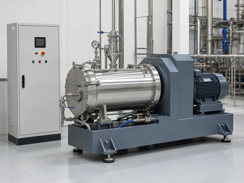
The short version
The Process in Four Steps
Think of a sand mill as a controlled contact zone: the pump brings material in, the rotor creates movement, the beads transfer energy, and the separator keeps the beads in the chamber.
Feed the Slurry
A pump moves the premixed liquid and suspended particles into the grinding chamber at a controlled rate.
Accelerate the Beads
Discs, pins or another rotor design create relative movement between the beads, slurry and chamber.
Transfer Energy
Particles repeatedly enter high-stress zones between moving beads and surrounding surfaces.
Separate and Discharge
A screen or dynamic separator retains the beads while allowing the processed slurry to leave.
Inside the chamber
Five Parts Work as One System
No single component “does the grinding” by itself. Milling is the result of interaction between flow, motion, media and heat control.
Pump and inlet
The pump controls how quickly slurry enters and therefore influences residence time, pressure and throughput.
Rotor, discs or pins
The rotating assembly creates bead circulation and velocity differences throughout the working zone.
Grinding beads
The beads carry mechanical energy to very small local contact zones around particles and agglomerates.
Screen or separator
The separator allows liquid product to pass while keeping the full bead distribution inside the chamber.
Cooling jacket
Cooling removes heat created by viscous flow and mechanical energy, helping protect the product and process stability.
Chamber and seals
The chamber contains pressure and media; the shaft seal keeps product inside around the rotating drive connection.
Particle reduction
What Actually Happens to the Particles?
Inside the chamber, particles experience many short stress events. The balance changes with bead size, density, rotor design, speed, viscosity and particle properties.
Impact
Moving beads collide and change direction. These local impacts can help fracture brittle particles or break larger agglomerates.
Shear
Nearby layers move at different speeds. The resulting shear can pull apart weakly bound agglomerates and improve dispersion.
Compression and Attrition
Particles are trapped briefly between surfaces. Repeated squeezing and rubbing wear down edges and reduce size over many contacts.
Grinding and dispersion are not always the same. Mineral particles may need true fracture. Pigment or battery-material slurries may mainly require agglomerates to be separated without damaging the primary particles.
Bead diameter
Why Smaller Beads Can Produce Finer Results
For the same chamber volume, smaller beads create far more individual beads and contact points. That can improve fine dispersion—but only when the feed, viscosity and separator are suitable.
More frequent contacts
Useful for fine targets and weak agglomerates when the mill can circulate and retain the media reliably.
More energy per bead
Useful when the feed is coarse, hard or highly resistant, but the number of contacts per chamber volume is lower.
Match the separator
The separator must retain the smallest supplied beads, not only the nominal or average bead diameter.
Operating window
The Main Variables Operators Control
Every adjustment changes more than one outcome. The goal is a stable window that reaches the particle-size target without excessive heat, wear, pressure or energy use.
| Variable | What it mainly changes | Typical trade-off |
|---|---|---|
| Bead size | Contact frequency and stress energy per contact | Smaller is not automatically better for coarse or resistant feed |
| Bead density | Momentum and ability to move through resistant slurry | Higher density can increase power demand and equipment stress |
| Media filling level | Number of active contacts and flow resistance | Too little wastes chamber volume; too much can raise pressure and heat |
| Rotor speed | Bead velocity and energy input rate | More speed can also increase temperature, wear and foaming |
| Flow rate | Residence time per pass and production throughput | Fast flow gives less processing per pass; very slow flow may reduce output unnecessarily |
| Solids and viscosity | Particle loading, bead mobility and hydraulic resistance | High viscosity can reduce circulation and raise pressure |
| Cooling | Product temperature and viscosity stability | Insufficient cooling can change the material and make results less repeatable |
| Separator clearance | Media retention and discharge stability | A poor match can cause blockage, bead loss or unstable flow |
Process modes
Single-Pass and Circulation Milling
The internal grinding principle stays similar, but the way material travels through the system changes how operators control fineness and throughput.
Single-Pass Mode
The slurry passes through the chamber once before moving to the next process stage.
- Simple material path
- Useful when one pass meets the target
- Requires stable feed and consistent residence-time conditions
Circulation Mode
The product returns to a holding tank and passes through the mill repeatedly until the target is reached.
- Easy to sample during gradual size reduction
- Useful for fine targets and batch control
- Tank mixing must prevent settling and uneven concentration
Common misunderstandings
Four Ideas That Cause Selection Errors
“The mill uses sand.”
Most modern sand mills use engineered beads selected for density, wear, chemistry and size consistency.
“More speed is always better.”
Extra speed may add energy, but can also increase heat, wear, foaming, pressure and damage to sensitive material.
“The smallest bead gives the finest result.”
Only when the feed is suitable, bead motion remains effective and the separator safely retains the full media range.
“The screen controls product size.”
The separator retains the grinding beads. Product particle size is mainly controlled by stress history and process conditions.
Stable operation
A Practical Way to Think About Start-Up and Control
Good operation is not a search for the highest speed. It is the controlled establishment of flow, bead motion, temperature and pressure inside a safe window.
Once the process is stable, consistent sampling can show whether particle size is still improving and whether the extra milling time is economically useful.
This overview explains principles, not a machine-specific operating procedure. Interlocks, permissible pressure, cooling, seal checks, filling method and shutdown sequence must follow the mill manufacturer’s manual and site safety rules.
General control sequence
- Confirm media, separator and slurry compatibility.
- Establish cooling and product circulation according to the machine procedure.
- Bring rotor speed and feed conditions into the approved operating window.
- Watch pressure, temperature, power, flow and unusual vibration or noise.
- Sample consistently and compare particle size, viscosity and product quality.
- Stop at the required endpoint instead of milling longer without a measurable benefit.
Common questions
Frequently Asked Questions
Is a sand mill the same as a bead mill?
In modern industrial use, the terms often describe the same basic equipment family. “Bead mill” better reflects the engineered grinding media normally used today.
Does the separator determine product fineness?
No. It mainly retains the beads. Product fineness depends on the particle stress history created by media, rotor, flow and operating time.
Why does a sand mill need cooling?
Most mechanical energy eventually becomes heat. Cooling helps keep viscosity, product chemistry, seals and process repeatability within an acceptable range.
Match the Grinding Media to the Mill and Slurry
Share your mill model, chamber volume, separator opening, feed particle size, viscosity, target fineness and purity limit. We can suggest a practical starting media type and bead-size range for a controlled trial.